| Home | Videos | Blog | Forum | Downloads | Contact us |
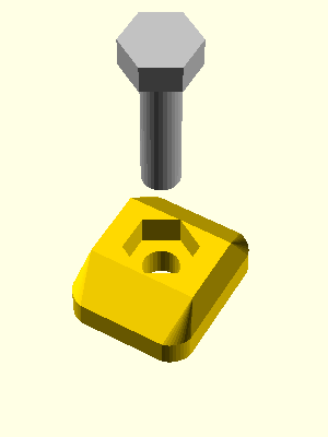
First step is to assemble the t-screws. Take a screw and a plastic t-nut and assemble them as follows:
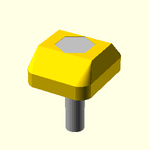
You should obtain an assembly like this:
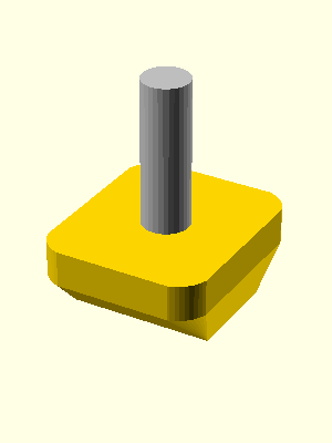
You should assemble various quantities of t-screws as shown below:
| Screw length | Quantity to assemble |
| 16 | 26 |
| 20 | 14 |
| 40 | 4 |
| 55 | 4 |
You need to prepare the pulleys first. Take a pulley and a M3x5 grub nut and screw it in the corresponding hole. Do the same for all 5 pulleys. Do not tight the nuts. You can tight them only when you put them on motors.
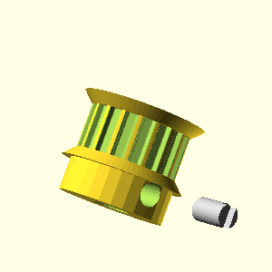
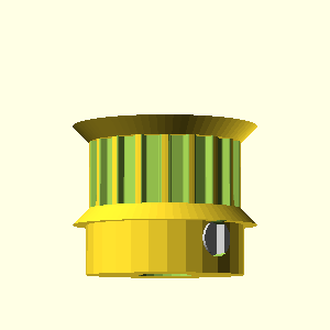
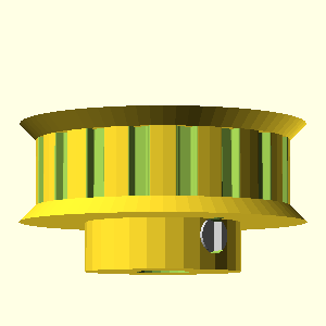
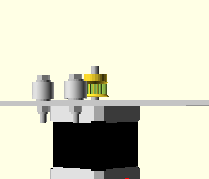
Take a 18-teeth pulley and insert it on the motor shaft. For X and Y axis the top of pulley must be exactly on the top of the motor shaft.
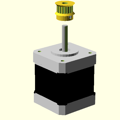
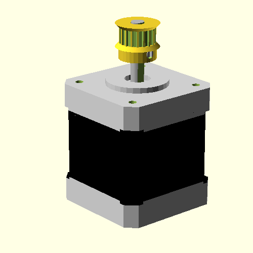
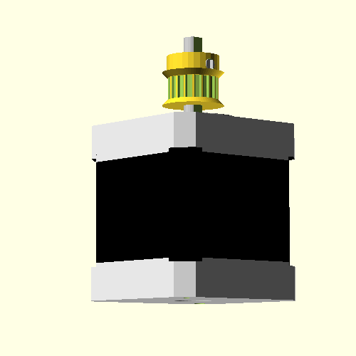
For Z axis the top of the pulley should be at 5 mm from the top of the motor shaft. Please note that pulley for Z axis is mirrored compared to X and Y axis.
Next take 2 Nema 17 stepper motors (for X and Y axis) and assemble them as follows. You also need (for each motor) 4 M3 screws of length 8mm and 4 washers of external diameter 9mm.
Tight the screws.
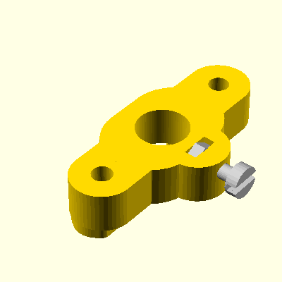
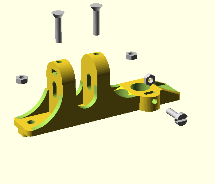
You need a shaft support, a M3x10 screw and an M3 nut. Make sure that the nut is rotated like in the picture below!
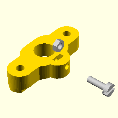
First insert the nut and then the screw. When you push the nut make sure that it will not rotate. Do not take tight the screw very well. It must be tighten only after you insert the shaft inside it.
Another shaft support is adjustable. It is used on the Y axis. You need 2x M3x15 screws and 2x M3 nuts.
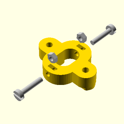
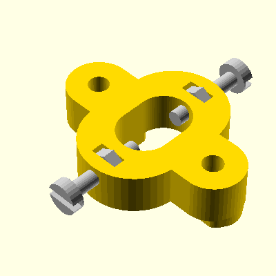
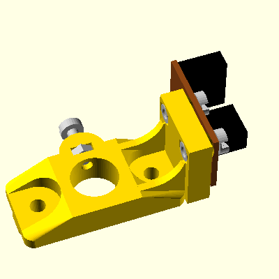
You need a shaft support, an M3x10 screw and an M3 nut, 2 M3x8 screws and 2 M3 nuts with autolock.
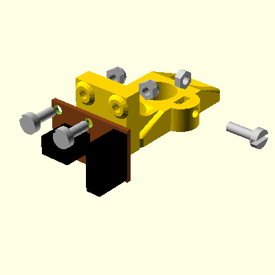
You should get something like this:
| Part number | Quantity | Description of part |
|---|---|---|
| x | 1 | Plastic part |
| x | 1 | M3x10 screw |
| x | 2 | M4x15 screw |
| x | 3 | M3 nuts |
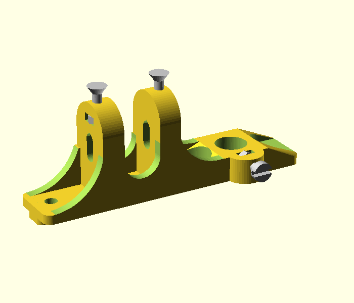
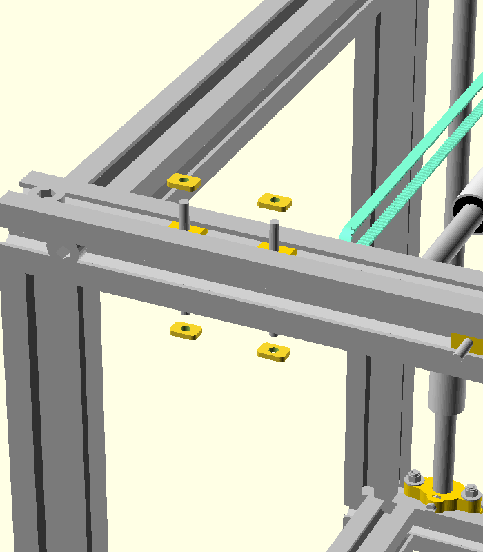
First of all please insert the nuts and then the screws. Please note the position of nuts. Do not rotate them, otherwise you will destroy the plastic part.
Do not tight the screws too much. Vertical screws are for tensioning the belt and should be tighten at the calibration moment.
| Part number | Quantity | Description of part |
|---|---|---|
| x | 1 | Part previously assembled |
| x | 1 | Timing belt of length 650 mm. |
| x | 1 | M4x35 sunken screw |
| x | 1 | M4 autolock nut |
| x | 3 | 4.3x9 washers |
| x | 2 | 624rs radial bearings |
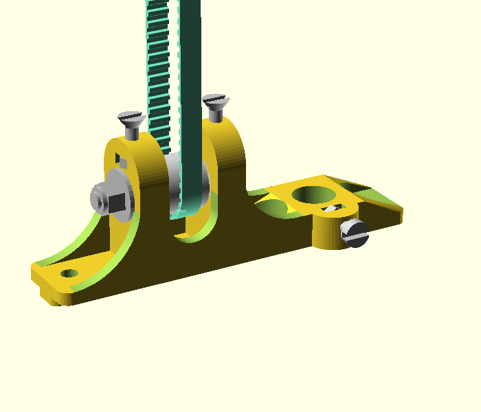
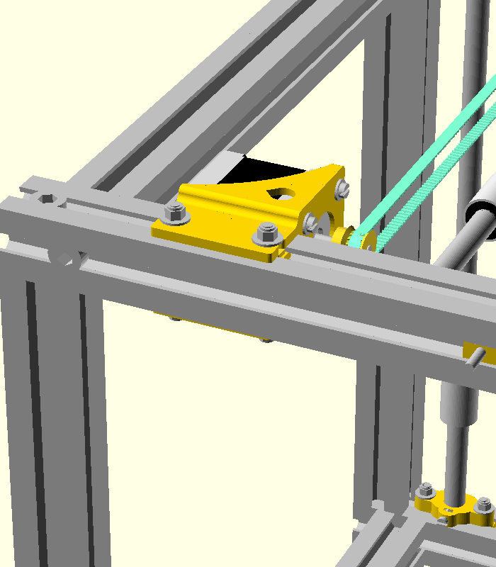
You need an M4x35 screw with sunken head, 1 M4 autolock nut, 3 washers with external diameter 9 mm, 2 radial bearings with interior diameter 4 mm and 1 timing belt of 650 mm.
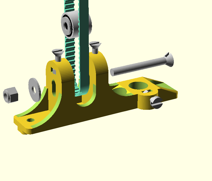
Make sure that you don't forget the belt outside! Also, do not tight the M4 autolock nut too well, so that the screws with bearings can easily slide in their location.
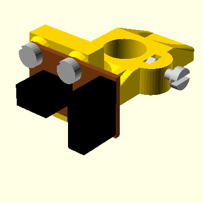
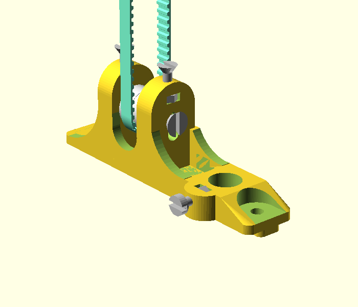
Here is a picture from a different angle.
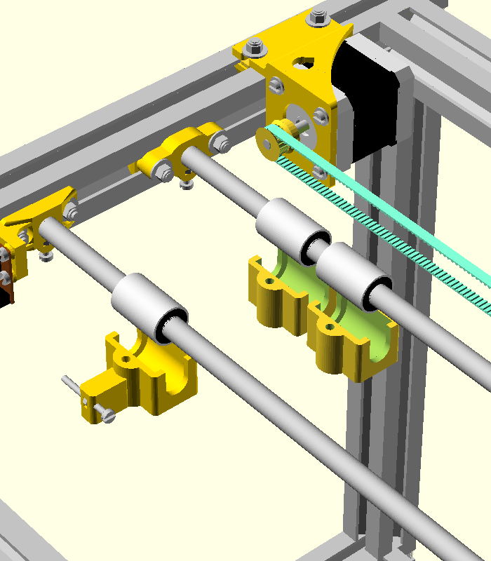
There are 3 linear bearing housing with screw: one is for Z axis and 2 identical are for X and Y.
For Z axis you need a linear bearing housing, an M3x50 screw and an M3 nut.
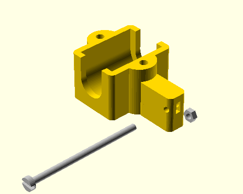
First insert the nut and then the screw. The screw must enter in the opto sensor up to the middle of the sensor. Fine tuning of the actual position of the screw will be set when you turn on your printer.
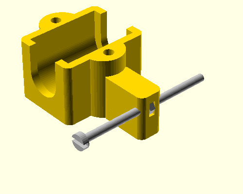
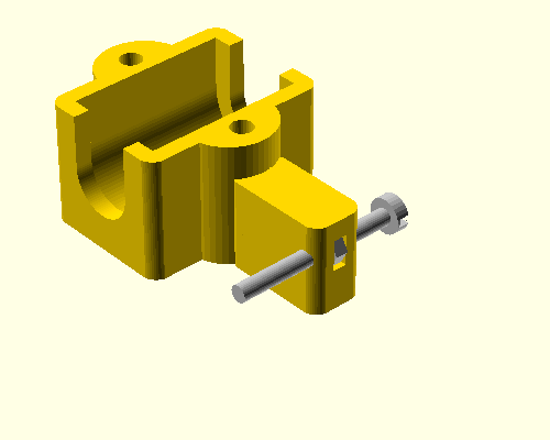
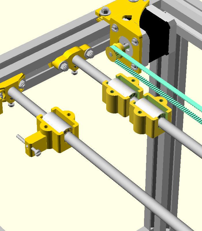
Do the same for the other 2 linear bearing housings (for X and Y). Please note that here the direction of the screw is inverted!
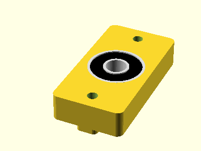
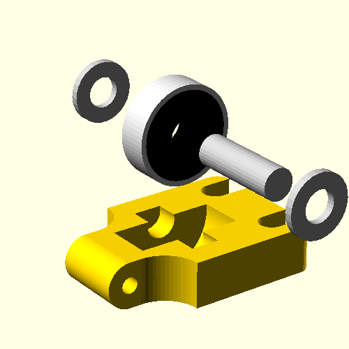
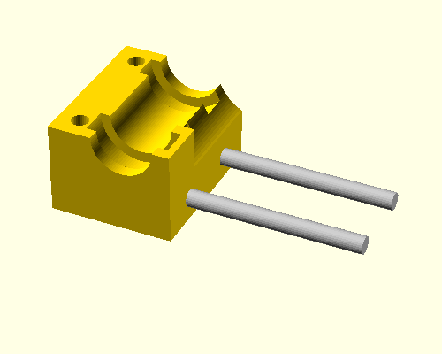
Take a plastic part and a radial bearing with internal diameter of 8 mm.
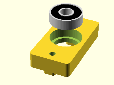
Insert the bearing in the plastic part.
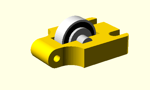
Take a plastic part and a radial bearing with internal diameter of 8 mm.
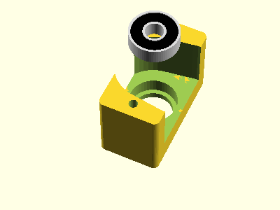
Insert the bearing in the plastic part.
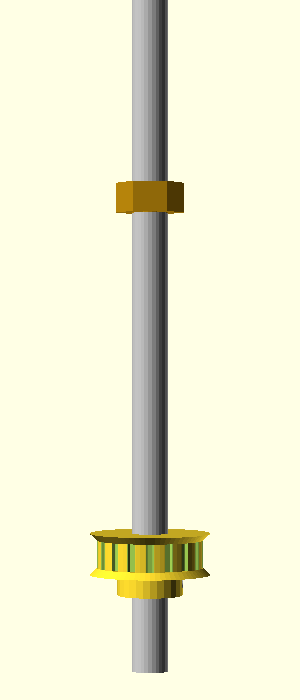
You need 1 M4 screw of length 300 mm, 1 pulley and 1 M8 nut made of brass. Prepare 2 parts like this, Make sure that the nuts are at exactly the same distance from the same.
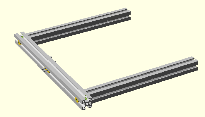
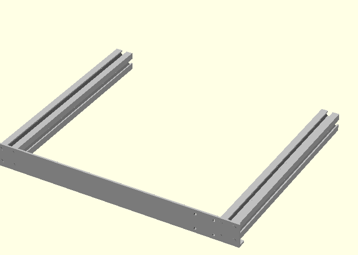
You need 4 profiles and 4 M8 screws with inbus head.
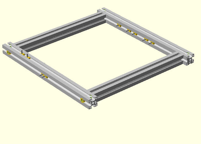
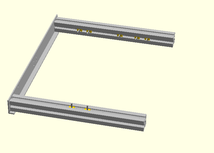
Here is how the bottom frame should look like:
Top view of the bottom frame
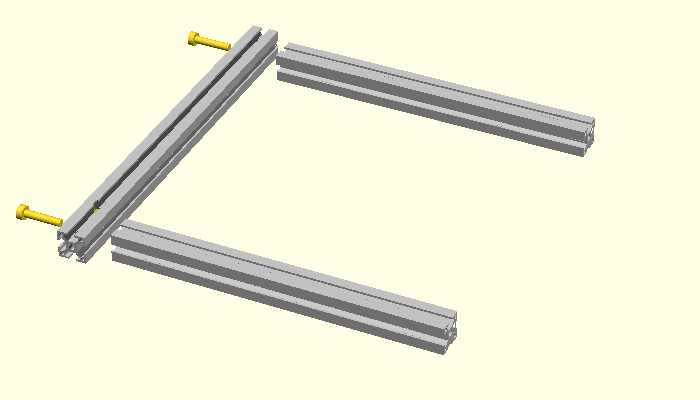
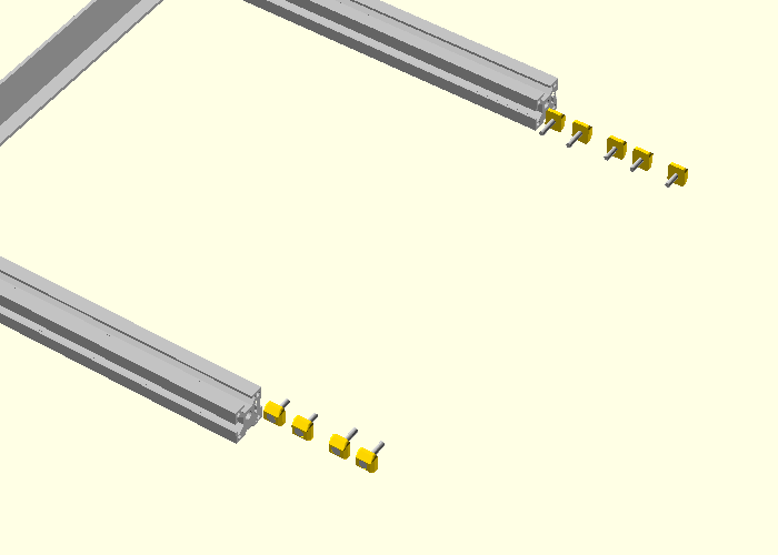
Insert the t-screws now
On the left side you need to insert them in this order: 2x length 55, 2x length 40, 2x length 20.
On the right side you need to insert them in this order: 2x length 20, 2x length 55, 2x length 40.
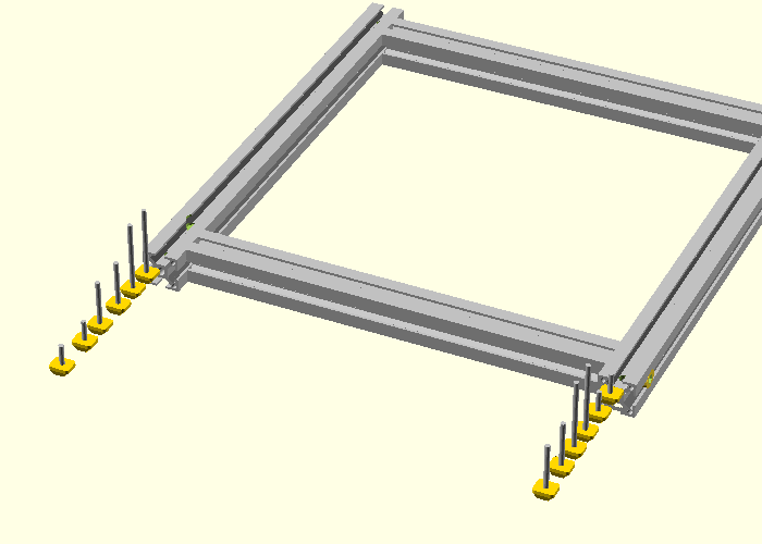
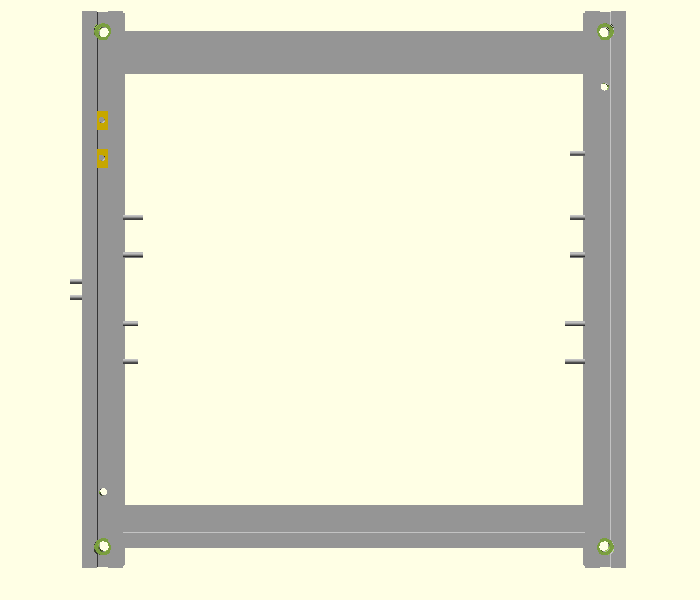
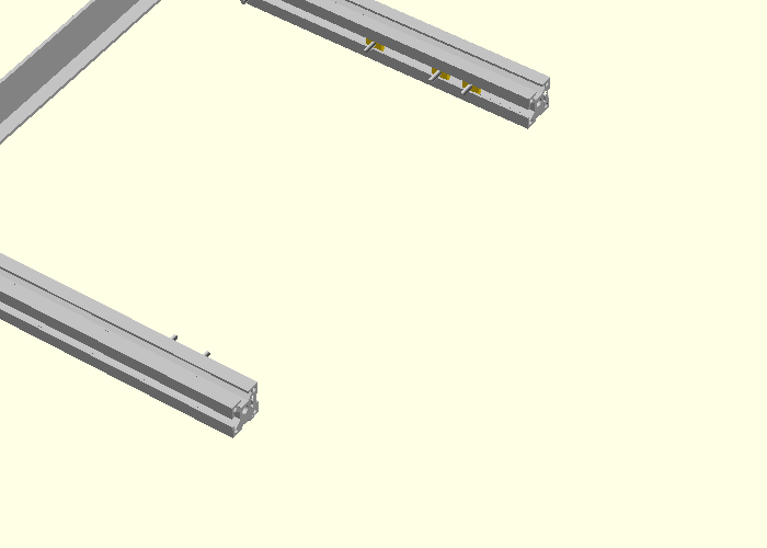
You should obtain something like this:
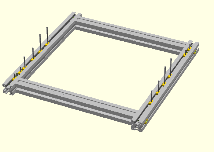
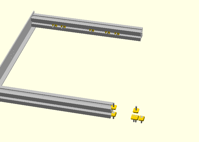
Viewed from top it should look like this:
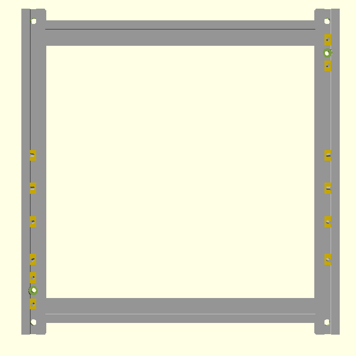
The exact position of the t-screws is not very important now. Only make sure that the 20 mm long t-screws are on different sides of the 12mm diameter hole. A 12 mm shaft will be inserted in that hole, and the t-screws will fix it on the frame.
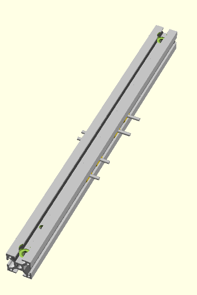
Left side profile. Insert 2x t-screws of length 16 on the left side and 2x t-screws of length 20 on the right side and then 2x t-screws of length 16 on the right side.
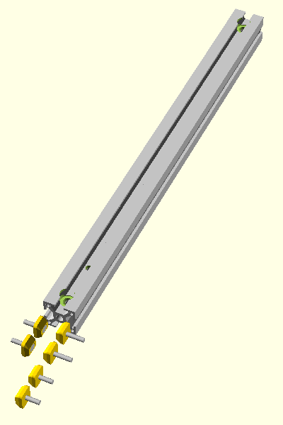
You should obtain something like this:
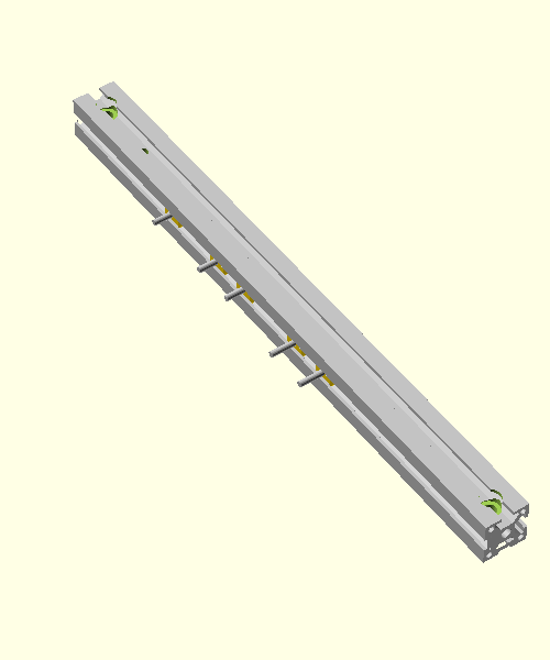
For right side profile insert 3x t-screws of length 16 and then 2x t-screws of length 20.
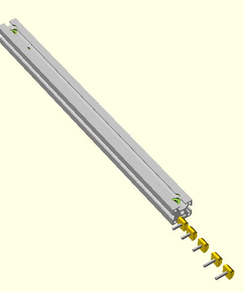
You should obtain something like this:
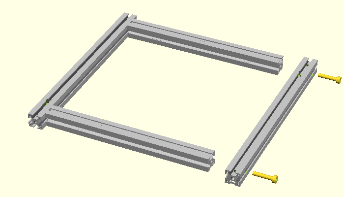
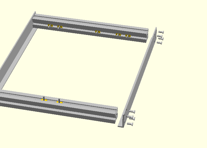
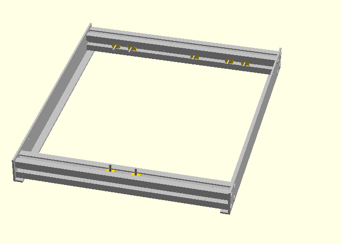
Now lets assemble the top frame. Take the left side profile (which has been previously prepared), 2 more profiles and 2 screws M8 with inbus head.
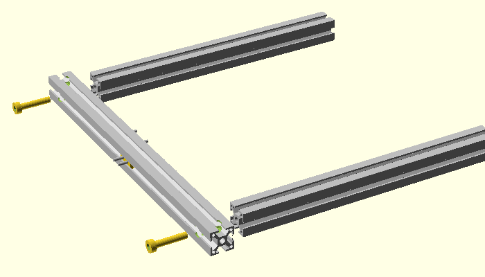
After tightening the screws you should obtain something like this:
Now take the right side profile (prepared previously) and 2 more M8 screws.
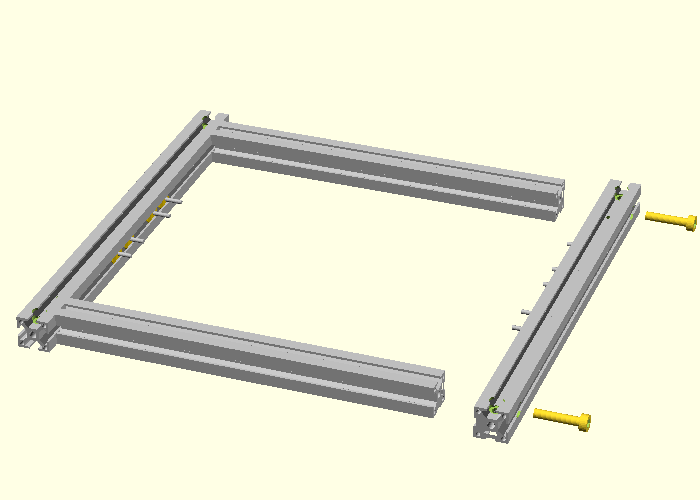
After tightening the screws you should obtain something like this:
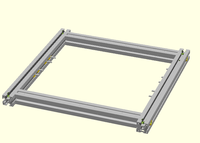
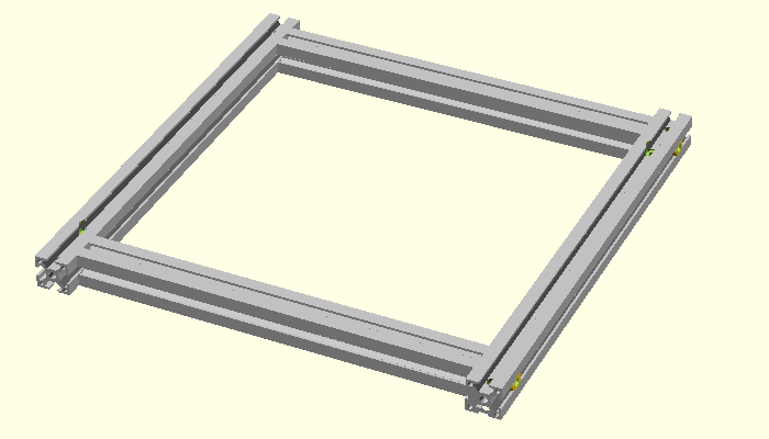
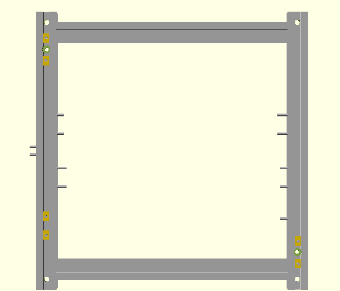
Insert t-screws on the top and bottom of the profiles. You need 6 on the left side and 2 on the right side. All have length 16.
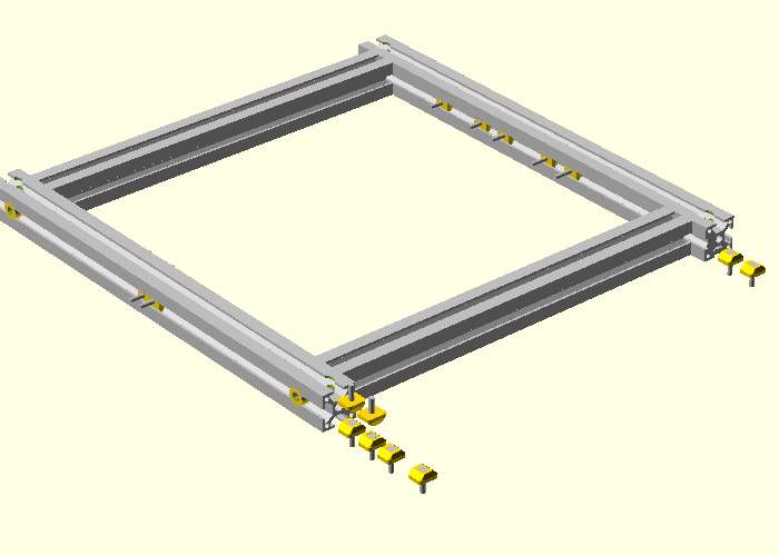
You should obtain something like this:
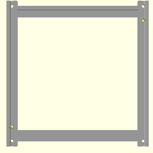
Viewed from top it should look like this:
Viewed from bottom it should look like below. Make sure that you have the t-screws on each side of the hole for shafts!
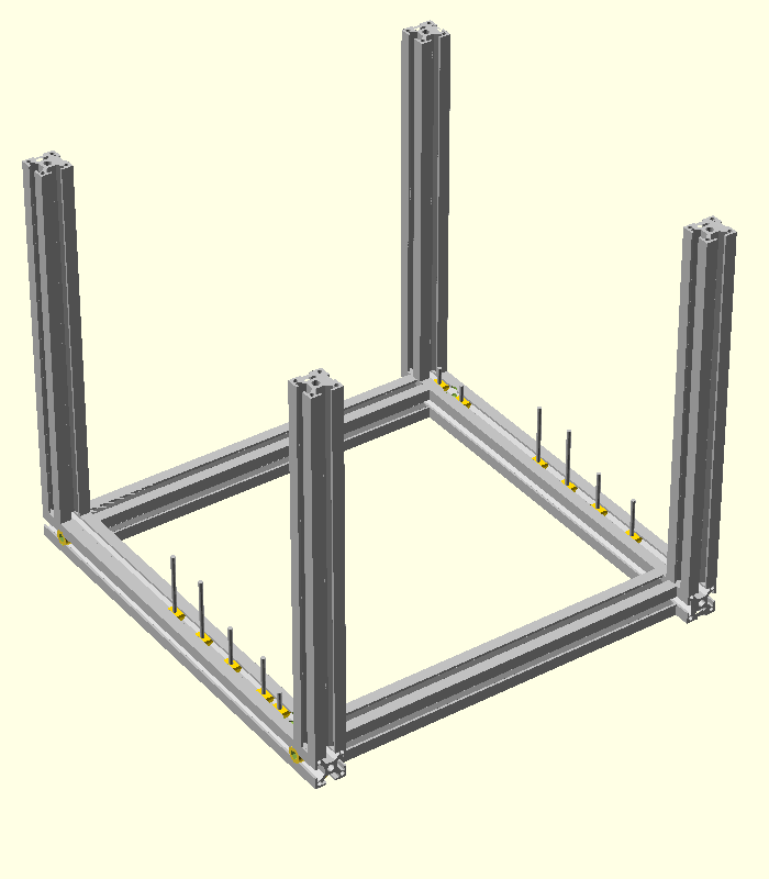
Take the bottom frame (previously assembled), 4 profiles and 4 M8 inbus screws.
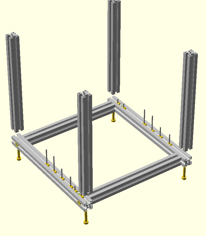
Tight the screws.
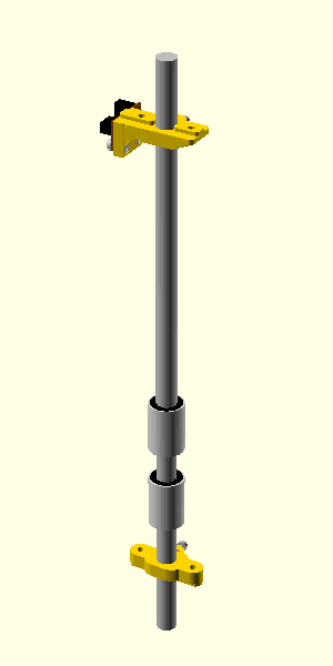
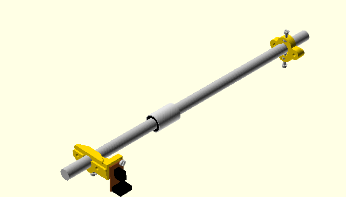
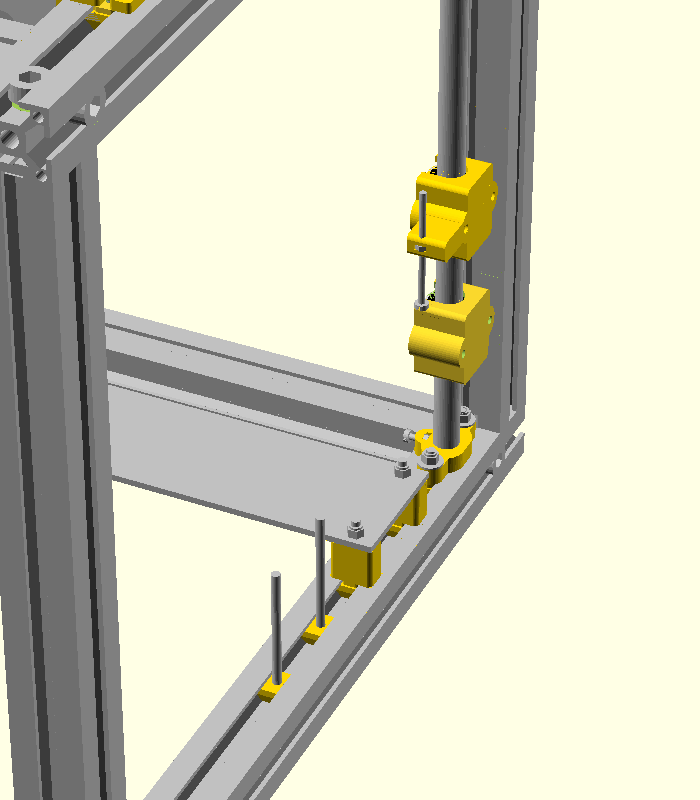
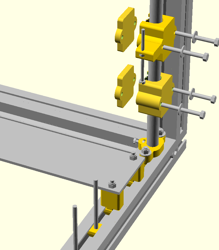
Z-shaft left. Take a 12 mm shaft, insert 2 lm12uu linear bearings and one shaft support at the base and another shaft support with opto sensor at the top.
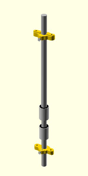
Z-shaft right. Take a 12 mm shaft, insert 2 lm12uu linear bearings and one shaft support at the base and another (identical) shaft support at the top.
Insert the shafts into bottom frames. Make sure that each shafts enters at least 7 mm in the frame.
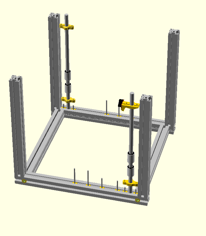
Take the top frame (previously assembled) and 4 M8x40 inbus screws.
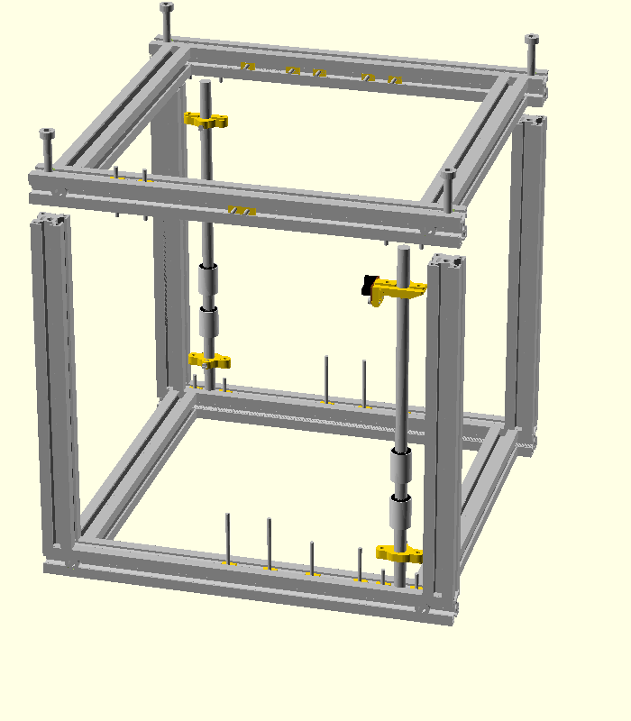
Tight the M8 screws.
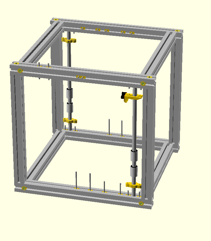
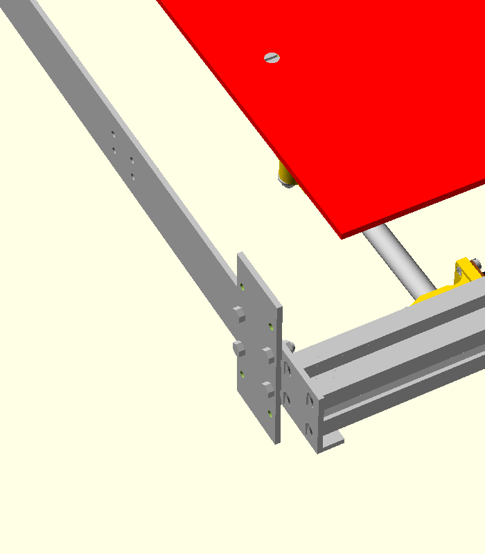
For each shaft push the plastic parts into the corresponding screws (both top and bottom).

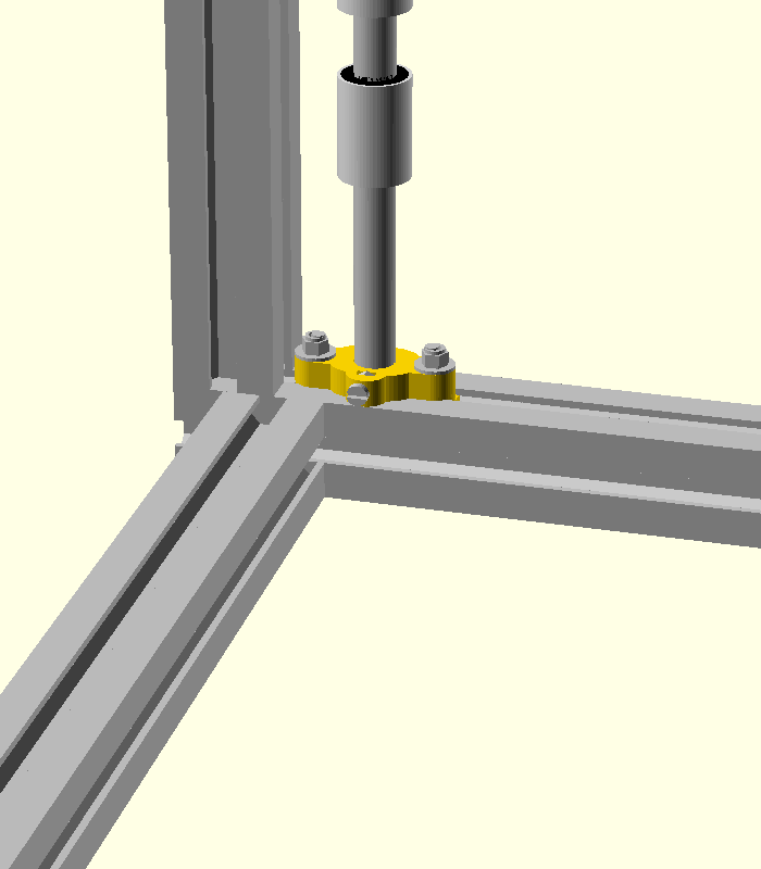
Now you need 8 washers and 8 M4 autolock nuts in order to fix the plastic parts on the aluminium profile.

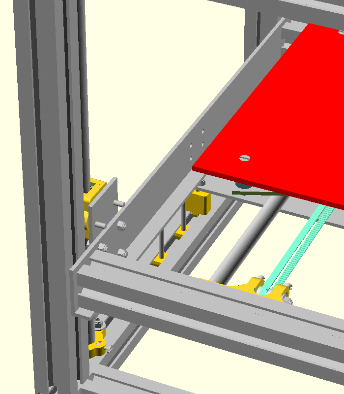
A closer look for one of the corners is below.
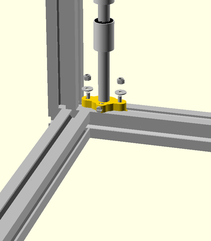
Tight the nuts and the M3 screws.
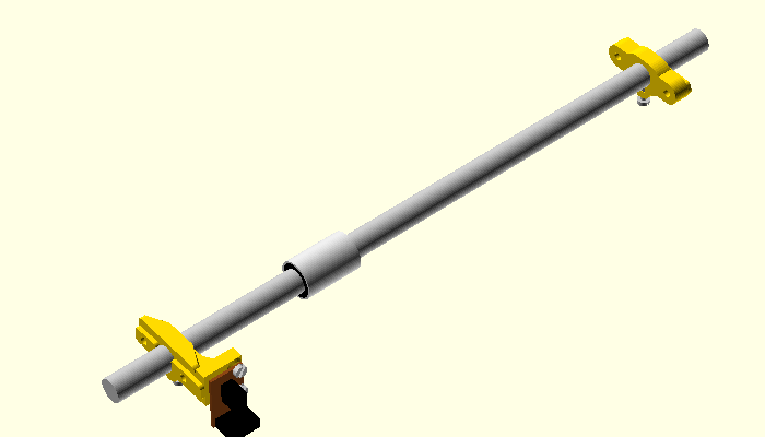
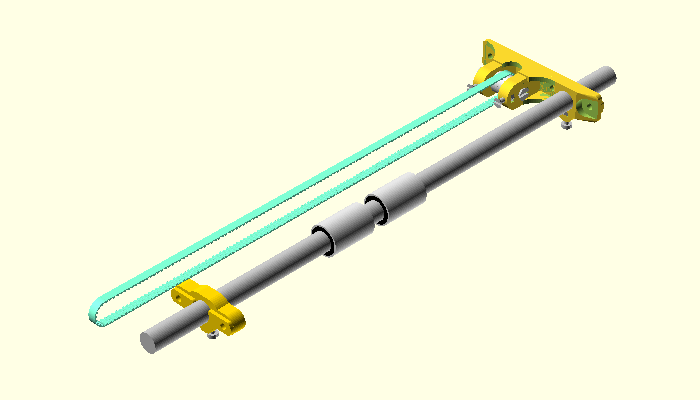
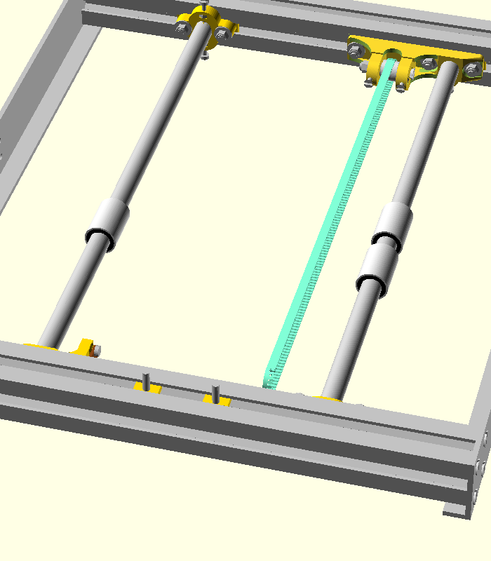
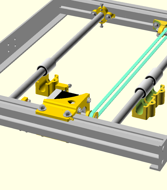
X-shaft 1. Take a 10 mm shaft, insert one lm10uu linear bearings and one shaft support at the right and another shaft support with opto sensor at the left.
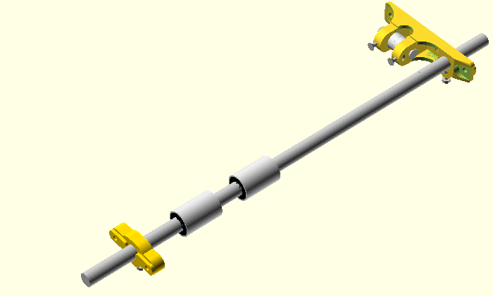
X-shaft 2. Take a 10 mm shaft, insert two lm10uu linear bearings and one shaft support with belt tensioner at the right and another shaft support at the left.
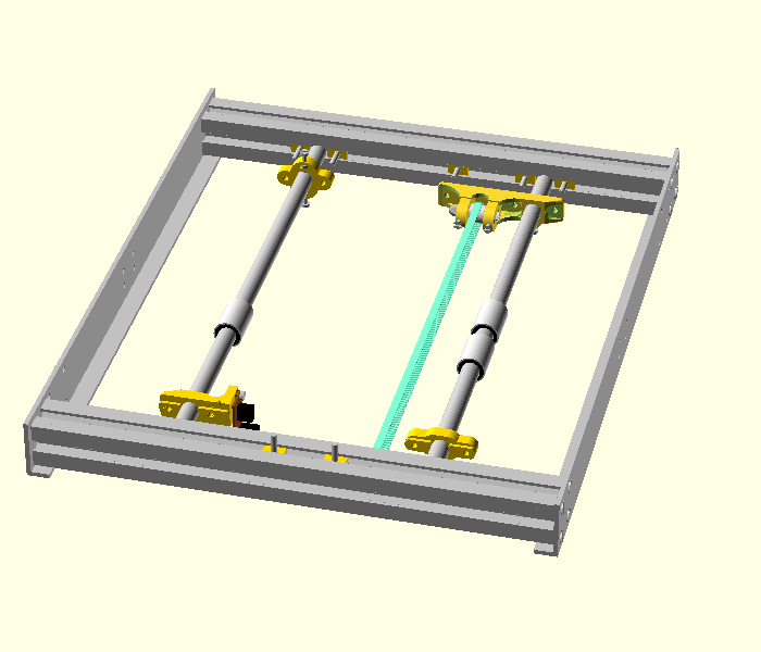
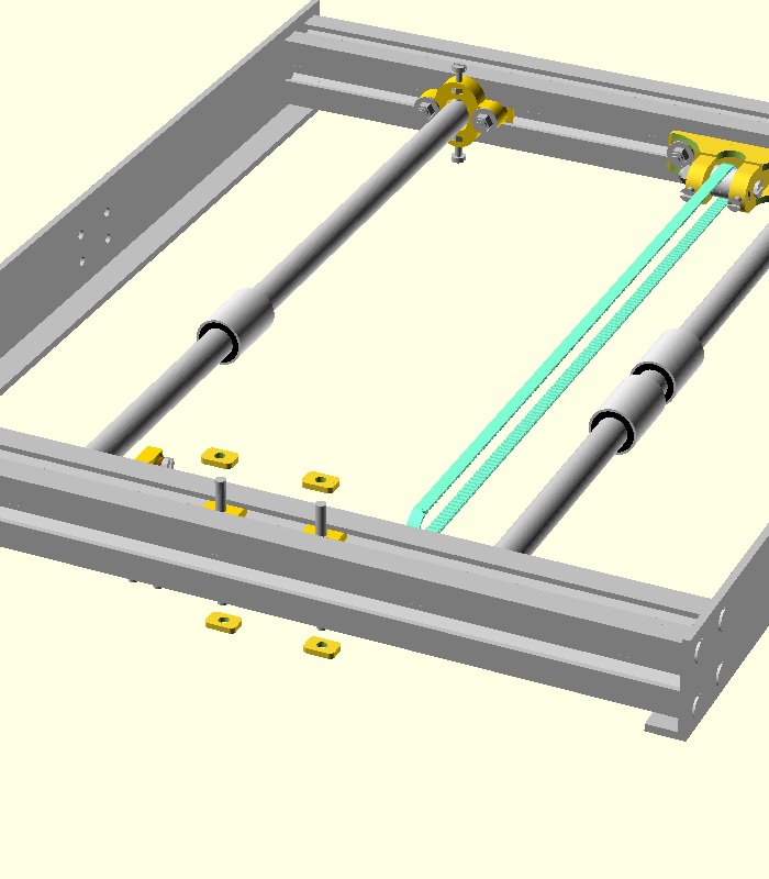
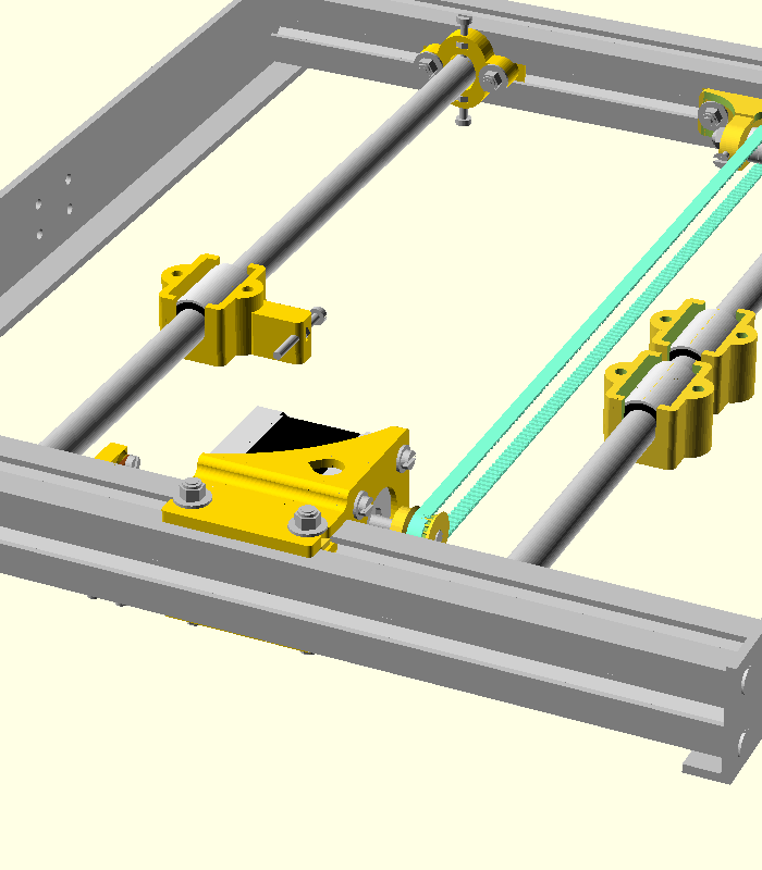
Put the x-shafts on the printer.
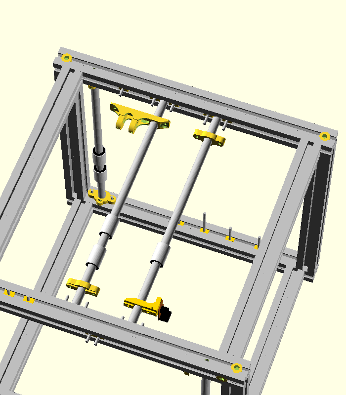
For each shaft push the plastic parts into the corresponding screws (both top and bottom).
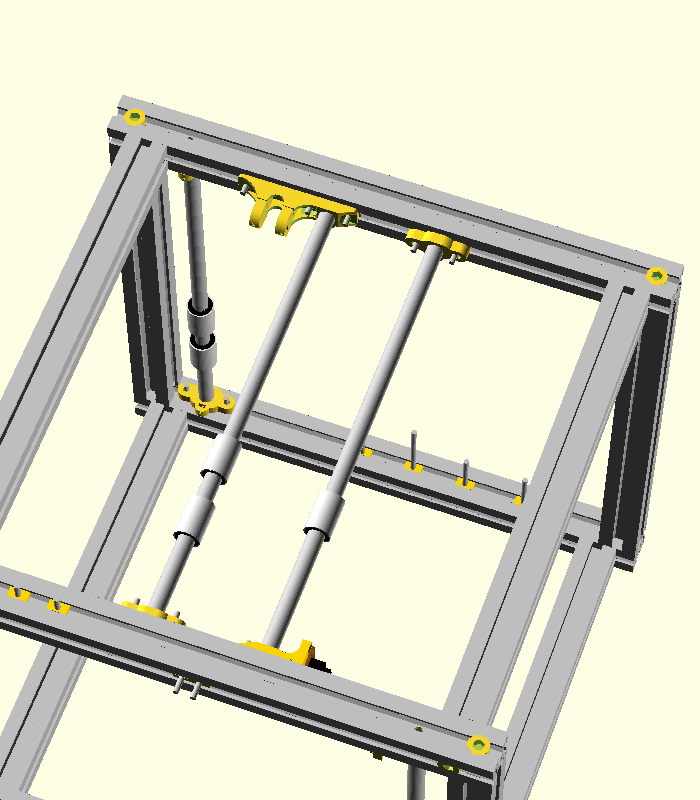
Take 9 washers and 9 M4 autolock nuts and secure them in position.

Do not tight the nuts very well. You can do this after you place the X axis carriage.

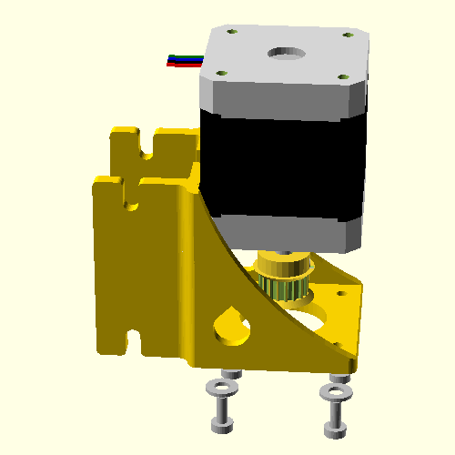
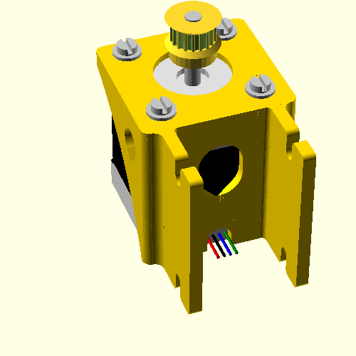
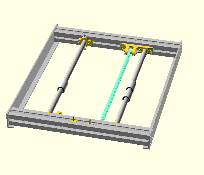
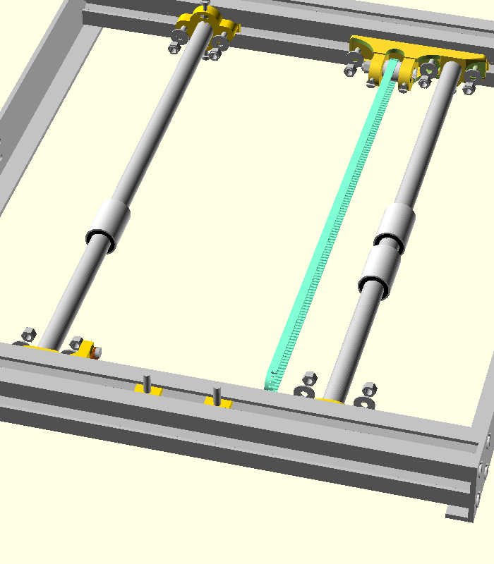
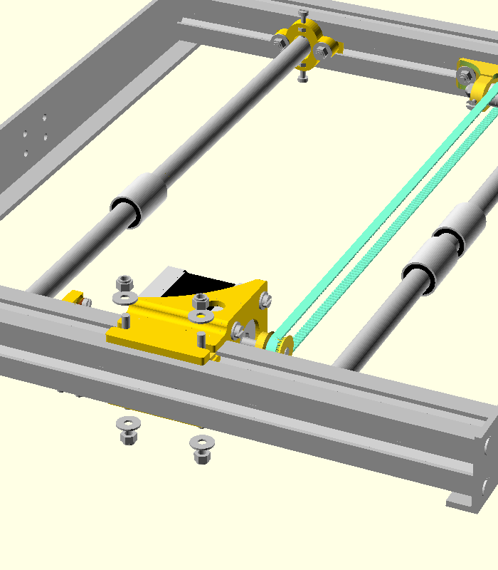
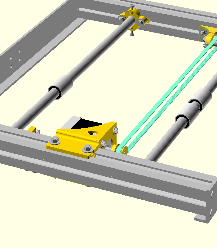
Take 4 spacers for the motor and insert them into position.
Take an already prepared motor with housing and place on the profile.

Also take 4 washers and 4 autolock nuts and fix the motor housing.

Make sure that the belt is at the same distance from the aluminium profile at both sides of the X axis. The belt must be parallel to the shaft.
| Part number | Quantity | Description of part |
|---|---|---|
| x | 1 | plastic part |
| x | 1 | plastic part |
| x | 3 | M4x35 sunken screws |
| x | 3 | M4 autolock nuts |
| x | 3 | 4.3x12 washers |
Tight the screws.
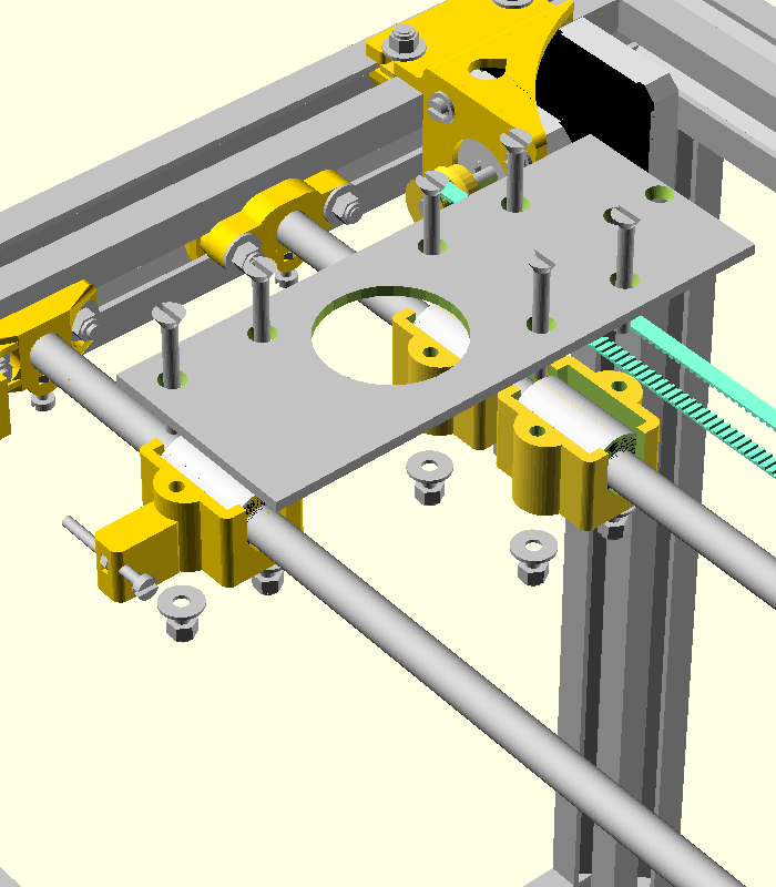
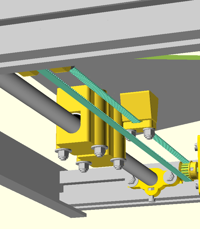
Now we need to fix the belt to the sheet of aluminium. The following parts are needed:
| Part number | Quantity | Description of part |
|---|---|---|
| x | 1 | plastic part |
| x | 2 | M4x20 sunken screws |
| x | 2 | M4 autolock nuts |
| x | 2 | 4.3x9 washers |

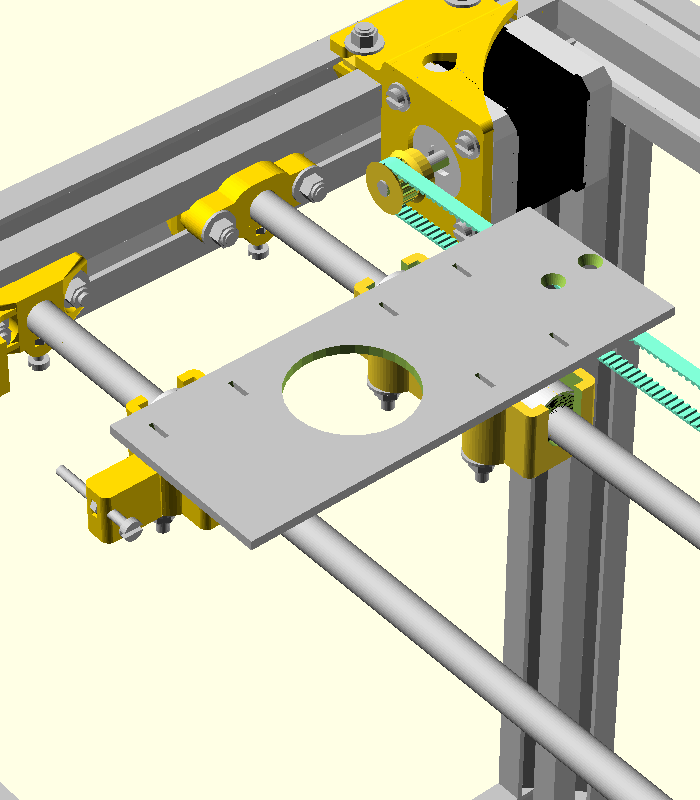
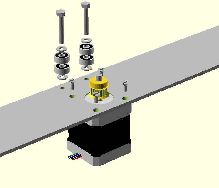
| Part number | Quantity | Description of part |
|---|---|---|
| x | 1 | Z aluminium sheet |
| x | 1 | Z motor with pulley |
| x | 2 | M4x35 hexa nut |
| x | 4 | M3x8 sunken screws |
| x | 4 | 624rs radial bearing |
| x | 4 | Washers with external diameter 9mm |
| x | 2 | M4 autolock nuts |
Tight the nuts well.
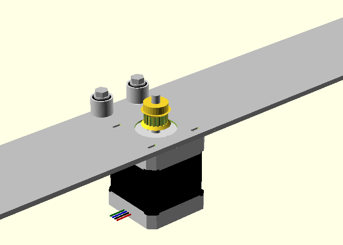
Here is a lateral view of the nuts.
| Part number | Quantity | Description of part |
|---|---|---|
| x | 1 | Z table |
| x | 4 | M4 autolock nuts |
| x | 4 | Z spacers - plastic parts |
Do not tight the nuts very well. This table must be moved in order to tension the Z belt.
Take a L profile, 2 profiles of length 334 and 8 M5x10 sunken screws. Note that there are 4 additional holes in the right side of the L profile. These holes are used for fixing the Y frame on the external frame.
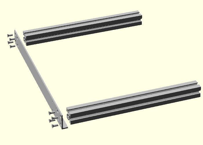
You should obtain something like this.
Insert 2-12 mm t-screws and then 2-20 mm t-screws on the profile next to you. Then insert 2-20 mm t-screws and then 3-12 mm t-screws on the other profile.
You should obtain something like this.
Still more t-screws are needed here: 4 for fixing the motor housing and 2 for fixing the Y-power cables.
After inserting them you should obtain something like this:
Take the other L profile and 8 M5x10 sunken screws and assemble them as follows:
After tightening the screws you should obtain something like this. Please notice the position of the holex for fixing the Y frame on the large frame.
Prepare the Y shafts.
Put the shafts on the frame.
Push the plastic parts until they touch the profiles.
| Part number | Quantity | Description of part |
|---|---|---|
| x | 9 | 4.3x12 washers |
| x | 9 | M4 autolock nuts |
Do not tight the nuts very well. The actual distance between shafts will be set when the Y sheet will be placed on position.
| Part number | Quantity | Description of part |
|---|---|---|
| x | 4 | Motor housing spacers |
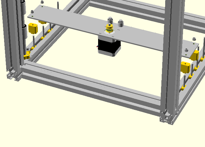
Take a motor housing previously assembled in insert it in the profile.

| Part number | Quantity | Description of part |
|---|---|---|
| x | 4 | 4.3x12 washers |
| x | 4 | M4 autolock nuts |
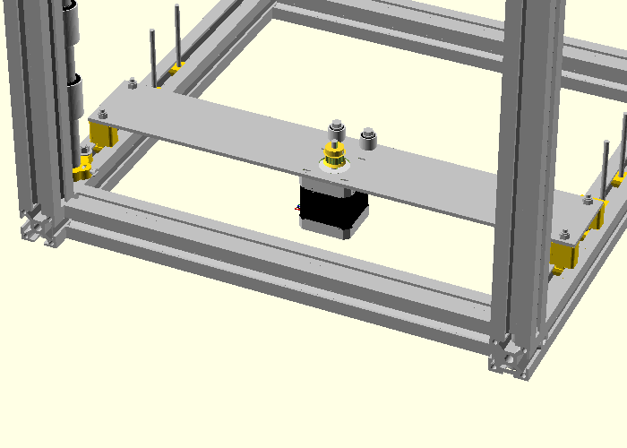
Tight the screws. Make sure that the belt is parallel with the shaft next to it.
| Part number | Quantity | Description of part |
|---|---|---|
| x | 2 | lm10uu bearing housing |
| x | 1 | bearing housing with screw - previously assembled. |
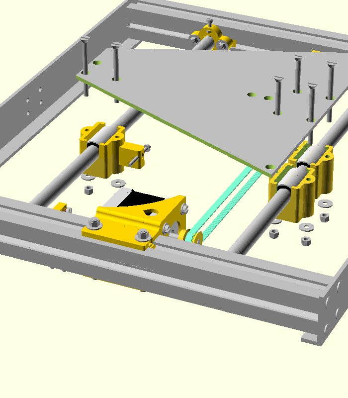
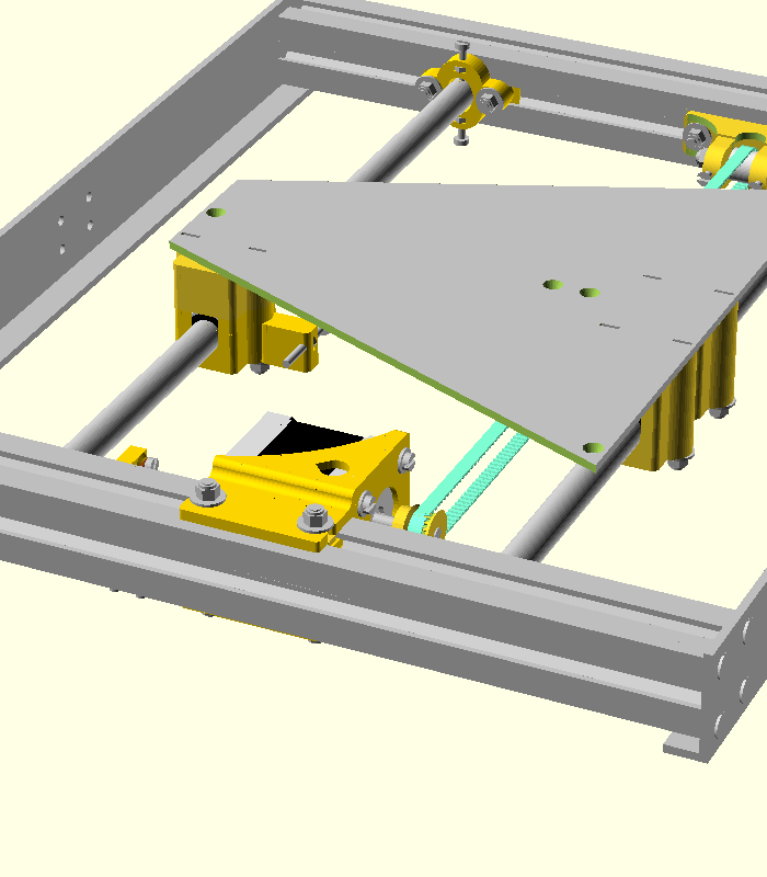
| Part number | Quantity | Description of part |
|---|---|---|
| x | 1 | trapezoidal aluminium sheet |
| x | 6 | M4x50 sunken screws |
| x | 6 | M4 autolock nuts |
| x | 6 | 4.3x12 washers |
Now we need to fix the belt to the sheet of aluminium. The following parts are needed:
| Part number | Quantity | Description of part |
|---|---|---|
| x | 1 | plastic part |
| x | 1 | plastic part |
| x | 3 | M4x35 sunken screws |
| x | 3 | M4 autolock nuts |
| x | 3 | 4.3x9 washers |
| Part number | Quantity | Description of part |
|---|---|---|
| x | 1 | 4 mm thick aluminium sheet of 250x250 mm |
| x | 3 | M4x30 sunken screws |
| x | 6 | M4 nuts - do NOT use autolock nuts here |
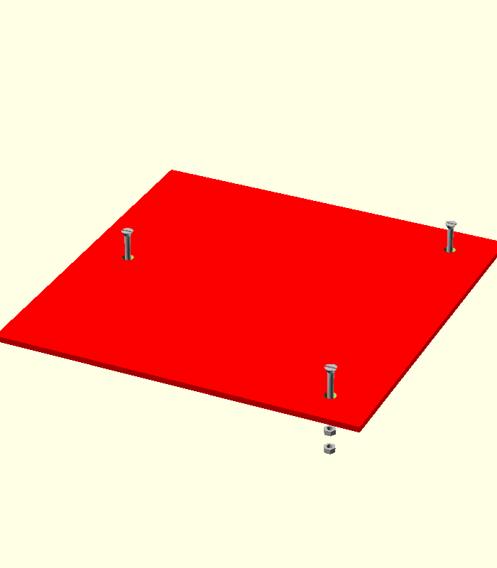
Tight the nuts in position.
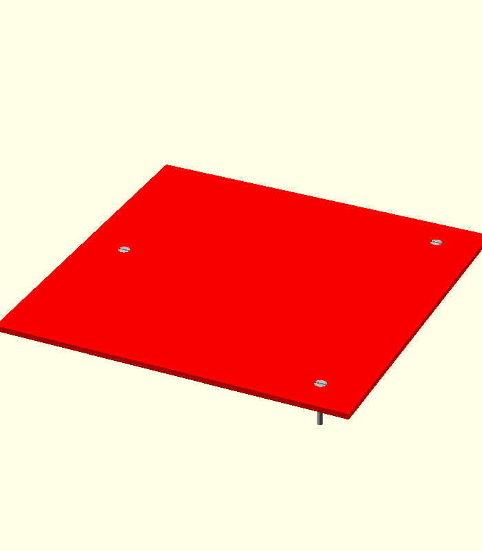
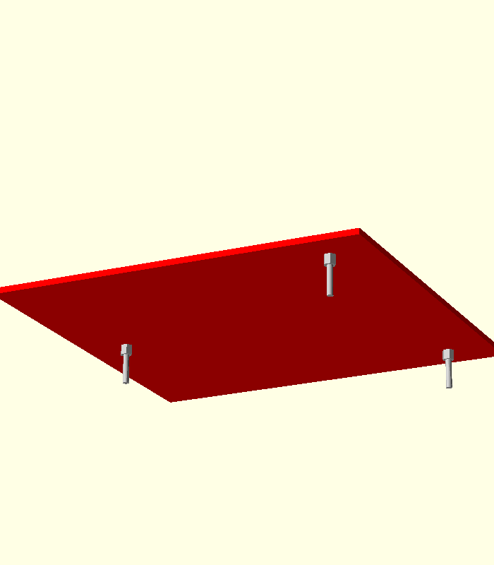
Here is another picture from the bottom of the print bed.
| Part number | Quantity | Description of part |
|---|---|---|
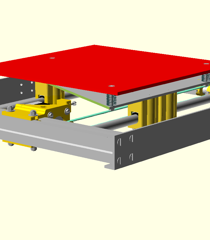
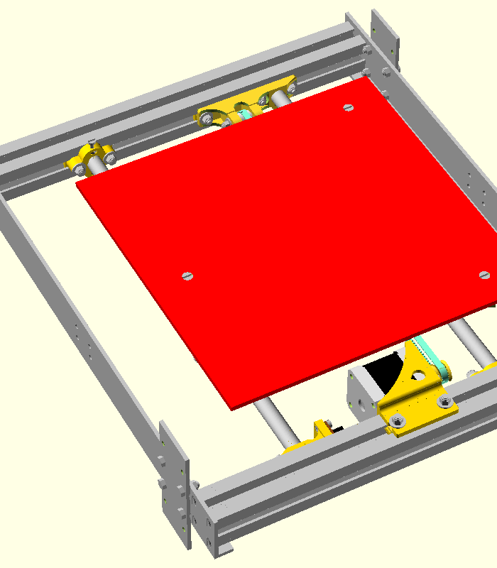
| x | 1 | Y axis previously assembled |
| x | 1 | Print bed previously assembled. |
| x | 3 | springs |
| x | 3 | M4 nuts - do NOT use autolock nuts here. |
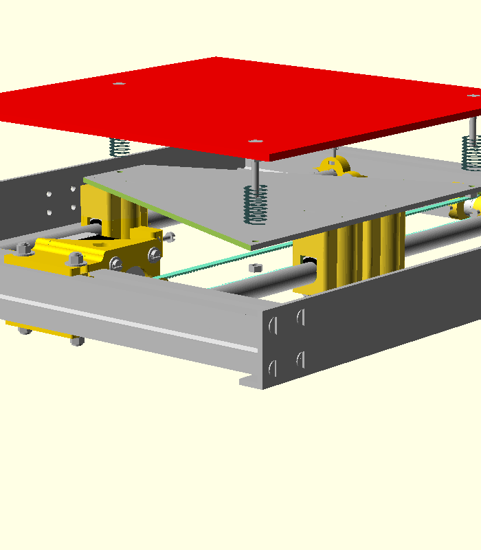
Tight the nuts a little bit. How much will be decided when you calibrate the printer.
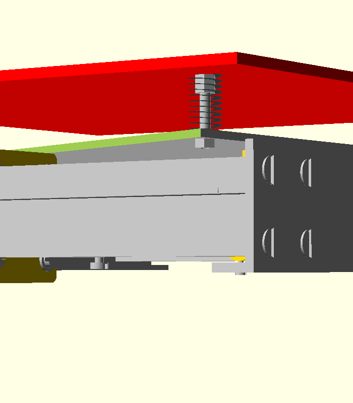
A close view of the assembly.
| Part number | Quantity | Description of part |
|---|---|---|
| x | 1 | Y axis previously assembled |
| x | 2 | aluminium sheets |
| x | 4 | M4x12 hexa screws. |
| x | 4 | M4 autolock nuts |
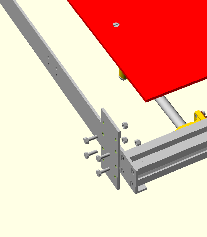
Tight the nuts very well.
Do the same for both sides.
| Part number | Quantity | Description of part |
|---|---|---|
| x | 1 | frame previously assembled |
| x | 3 | lm12uu bearing housings |
| x | 1 | lm12uu bearing housing with screw |
| Part number | Quantity | Description of part |
|---|---|---|
| x | 1 | frame previously assembled |
| x | 4 | Z spacers |
| x | 8 | M4x50 hexa screws |
| x | 8 | 4.3x12 washers |
Insert the Y axis into frame and push the M4x50 screws.
Use M4 nuts to secure the Y axis.

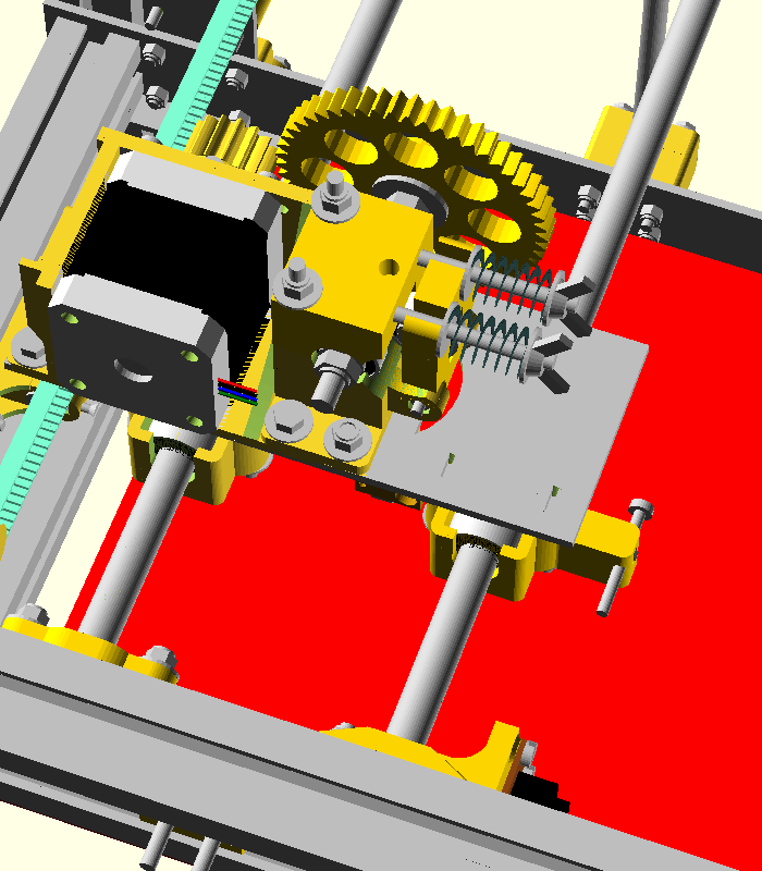
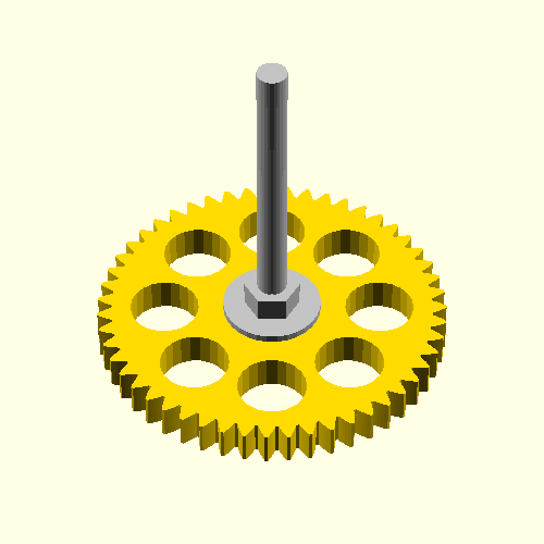
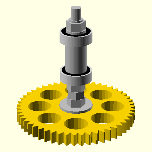
Take the large extruder wheel, a long M6 hexa screw, a large washer and a M6 nut.
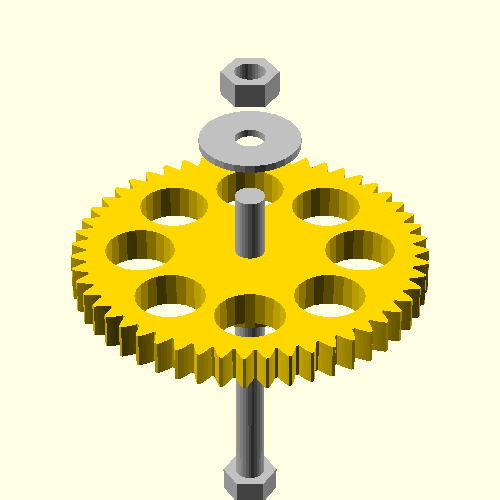
Tight the nut until the head of the screw enters completely in the heart of the extruder wheel.

Screw the following components on the long M6 screw: 2 M6 nuts, 1 washer, 1 radial bearing, 1 hobbed bolt, 1 radial bearing, 1 washer, 1 M6 autolock nut.
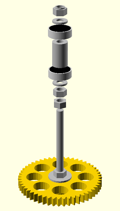
You should obtain something like this:
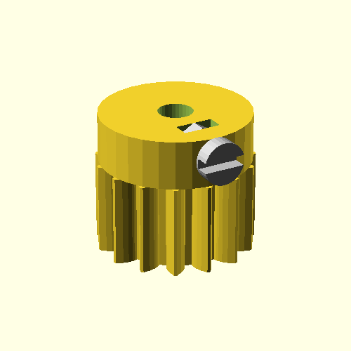
Prepare the motor gear. You need an M3 nut and an M3x10 screw. First insert the nut and then the screw. Take care so that the nut will not rotate in the plastic part.
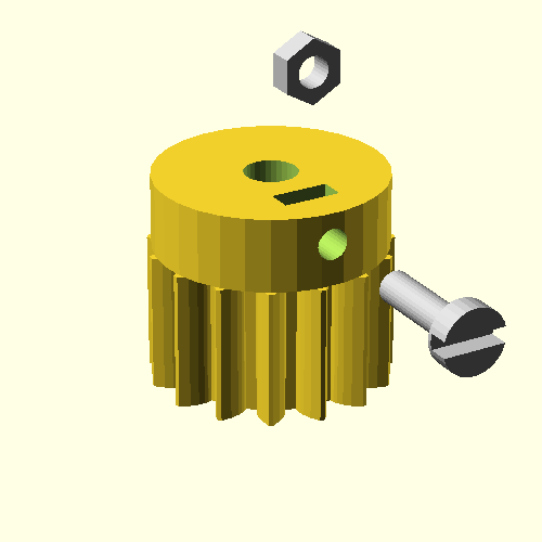
The assembled gear should look like this:
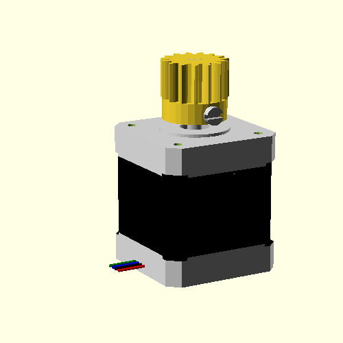
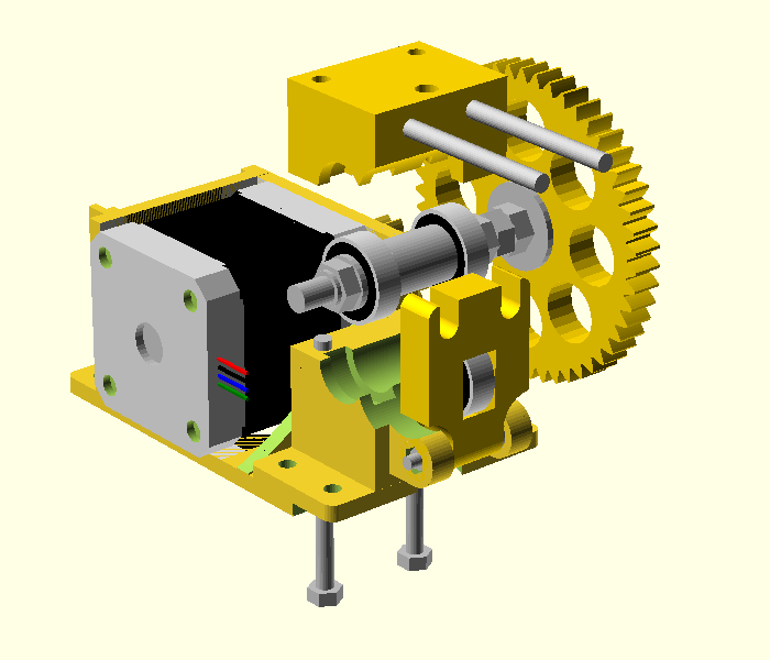
Take a motor and the previously prepared gear and assemble them.

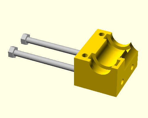
Prepare the plastic pusher. You need the plastic part, one 626 ridial bearing, 2 washers and a 6mm diameter shaft.
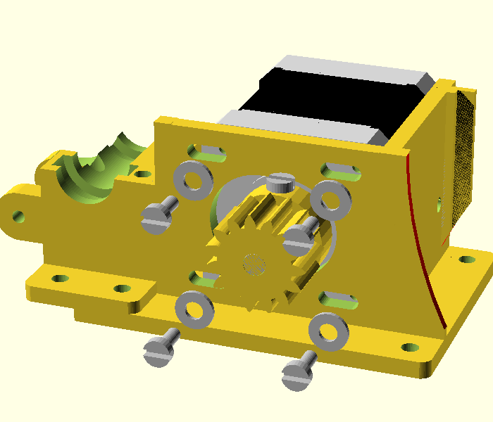
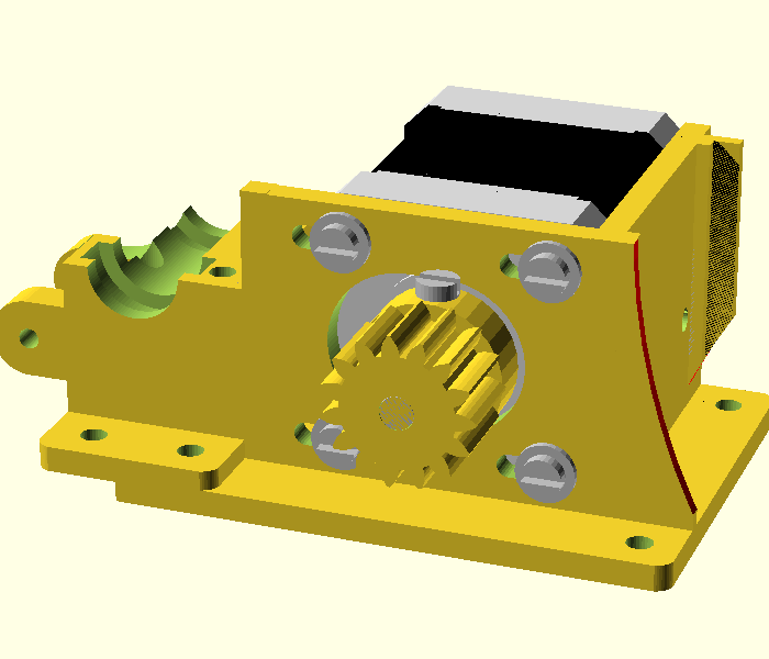
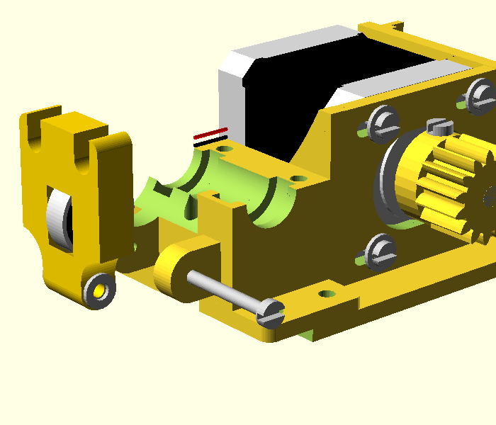
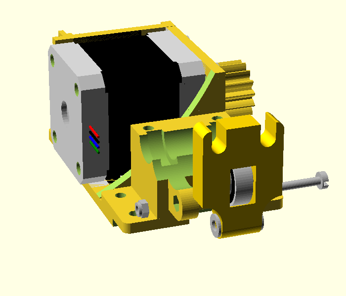
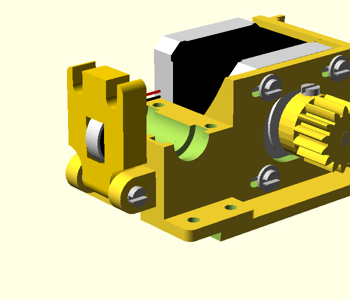
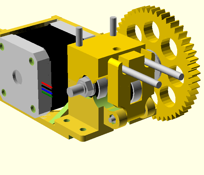
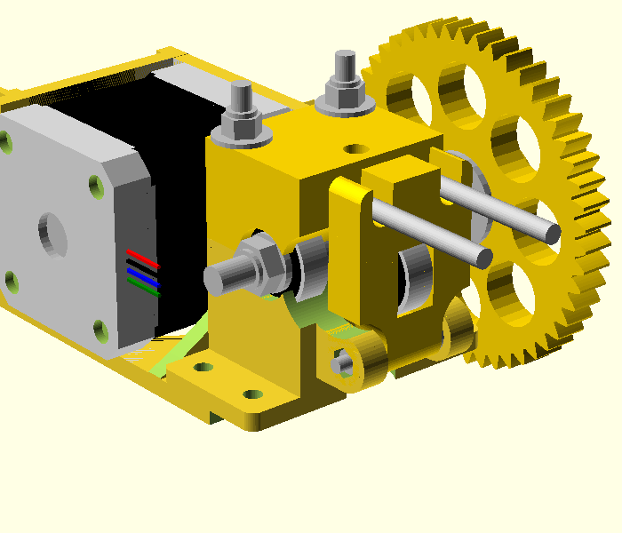
Insert the motor in the extruder base. You also need 4 washers and 4 M3x10 screws.Do not tight the screws very well ... this will be done after you insert the hobbed bolt too. Please also note in the below figures the position of the motor cables.
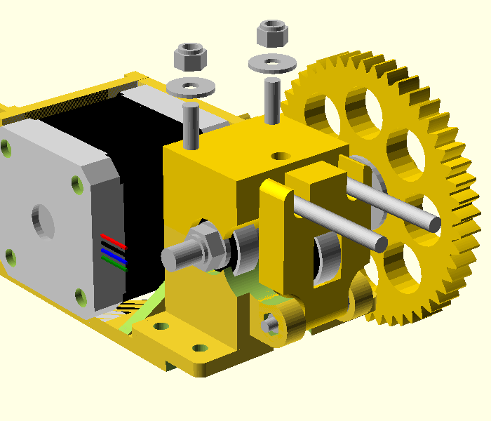
Attach the plastic pusher to the extruder base. For this operation you need a long M3x40 screw, 2 washers and 1 autolock M3 screw.
Take 2 M4x65 nuts and the extruder top housing and assemble them.
Take 2 M4x50 screws and insert them in the base. Then put the hobbed bolt and then the top housing.
Now take 2 washers and 2 M4 autolock nuts and tight them.
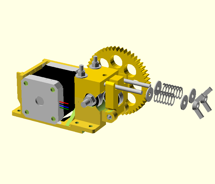
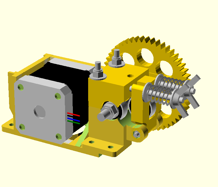
Now you need to put some pressure on the filament pusher. For this purpose you need 2 washers, 2 springs, 2 washers and finally 2 wing nuts.
Tight the wing nuts, but not very strong. The actual pressure will be set when you start printing.
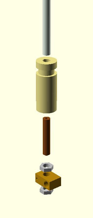
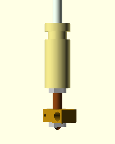
The following parts are needed: a (partially) threaded PTFE tube, a PEEK, a brass tube, 2 M6 slim nuts, and a heater block. Assemble them as in the figure below.
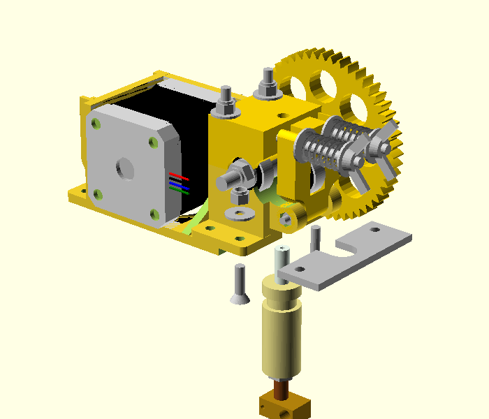
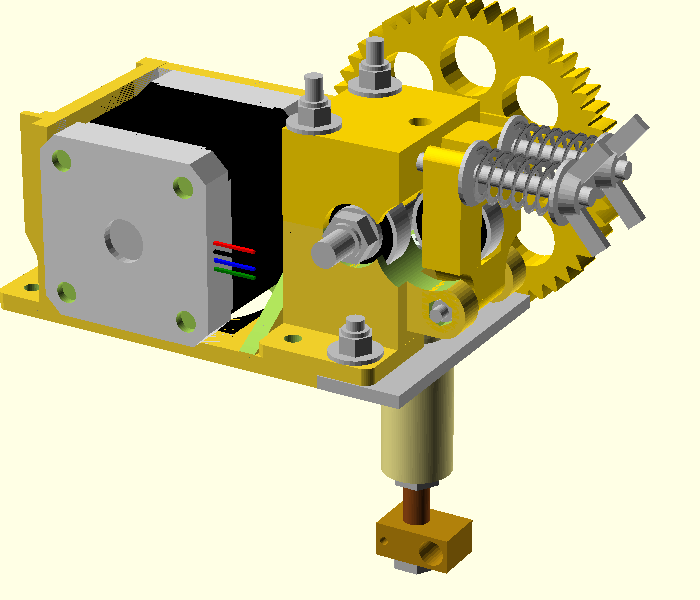
Now put the hotend in the extruder.
Place the extruder on the X carriage
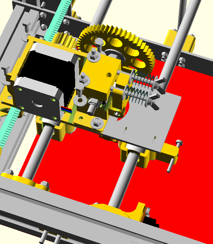
Tight the screws.